Rankine Cycle - Ideal Rankine Cycle Efficiency
Rankine Cycle Efficiency
Rankine cycle is a condensation process where steam is to be condensed into water.
Rankine cycle is nothing but a modification of Carnot cycle. Ideal Rankine cycle is very useful in steam power plants and gas power plants. To improve the efficiency of Rankine cycle in the steam power plant, there are some changes in Rankine cycle which differs from the Carnot cycle. Firstly, a pump is used in place of condenser to handle only liquid, not a mixture of liquid and vapour.Secondly, exhaust steam from the turbine is completely condensed in the condenser, see in the following diagram:
It is a reversible process. The Rankine cycle efficiency is much higher than Carnot cycle efficiency as because the pump is used in the Rankine cycle, which gives higher work ratio by doing significant proportion of turbine work.
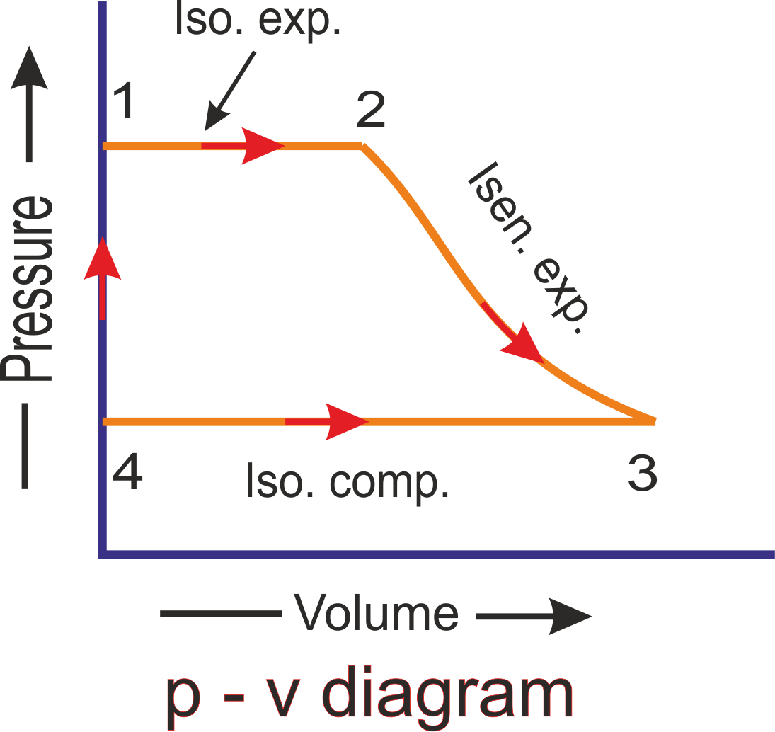
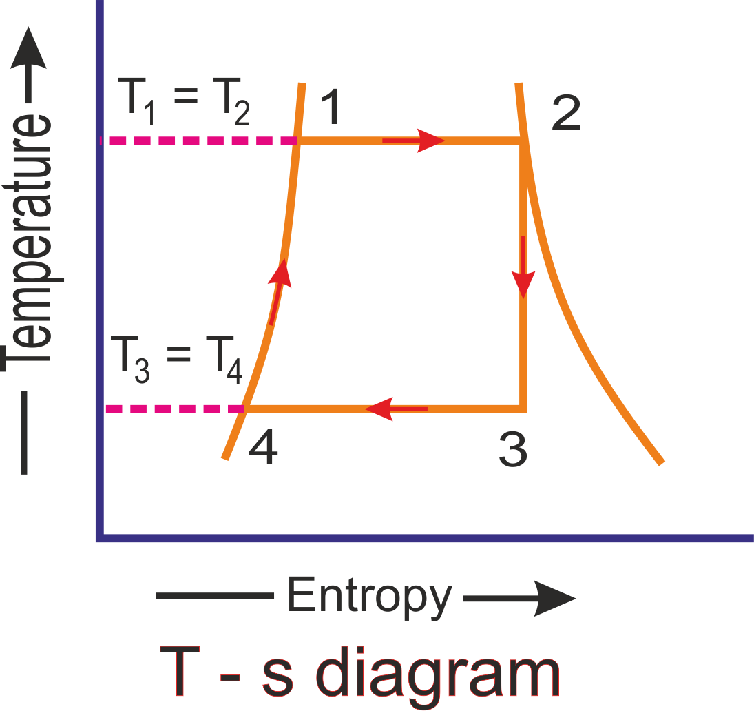
A simple Rankine cycle is completed by following four processes. Steam is used as a working substance in Rankine cycle, is shown the above p-v Rankine cycle diagram and T-s Rankine cycle diagram.
1).Process 1-2:
As we see in the above diaqgram, saturated water coming from hot well ata point 1 is isothyermally converted into dry saturated steam in a boiler and heat is absorbed at constant temperature T1 and pressure p1. The steam is now dry condition showing at point 2. The temperature and pressure at point 2 is T2 and p2 respectively. It is similar to the T1 and p1. This isothermal expansion process shown in the p-v and T-s curve 1-2. During isothermal expansion process, the heat absorbed by water denotes hfg1 which is similar to the hfg2 as a corresponding pressure p1 and p2.(since p1 = p2)
2).Process 2-3:
Now the dry saturated steam enters into the turbine. Here steam expands isentropically and the pressure and temperature falls down from p2 to p3 and T2 to T3 with a dryness fraction x3. During this expansion, no heat is supplied or rejected. So, there is no change in entropy and curve from 2-3 falls down show the above graph.
3).Process 3-4:
At this stage, Wet steam enters the condenser for condensation of steam. Heat is rejected in the condenser at a constant temperature T3 and pressure p3 until the total steam is condensed into water. At point 4 conditions, T3 = T4. So the curve of the p-v and T-s diagram is straight line and heat is rejected by steam is called latent heat equal to x3hfg3
4).Process 4-1:
Now water enters to the boiler at point 4 positions for warming. In the boiler, water is heated to a constant temperature T4 to T1 and volume. The pressure rises from p4 to p1. This operation is shown in the graph 4-1 on p-v and T-s diagram. The heat absorbed by water during this operation is equal to the sensible heat or liquid heat corresponding to the pressure p1 which is equal to sensible heat at point 1 minus sensible heat at point 4
Let,
hf1 = hf2 = Senseble heat or enthalpy of water at point 1 corresponding pressure p1 or p2 (since p1 = p2)
hf4 = hf3 = Senseble heat or enthalpy of water at point 4 corresponding pressure p4 or p3 (since p4 = p3)
So, Heat absorbed at warmed operation 4-1 = hf1 = hf4 = hf2 = hf3
and heat absorbed during the complete cycle is
= hfg2 + (hf2 - hf3) = hf2 + hfg2 - hf3 = hf2 - hf3
We know that heat rejected during the cycle
= h3 - hf4 = hf3 + x3hfg3 - hf4 = x3hfg3
Worhdone during the cycle is = Heat absorbed - heat rejected
= (h2 - hf3) - x3hfg3
= h2 - (hf3 + x3hfg3)
= h2 - h3
So, rankine cycle efficiency ηR is -