Centrifugal Pump | Working Principle Of Centrifugal Pump
WORKING PRINCIPLE OF CENTRIFUGAL PUMP
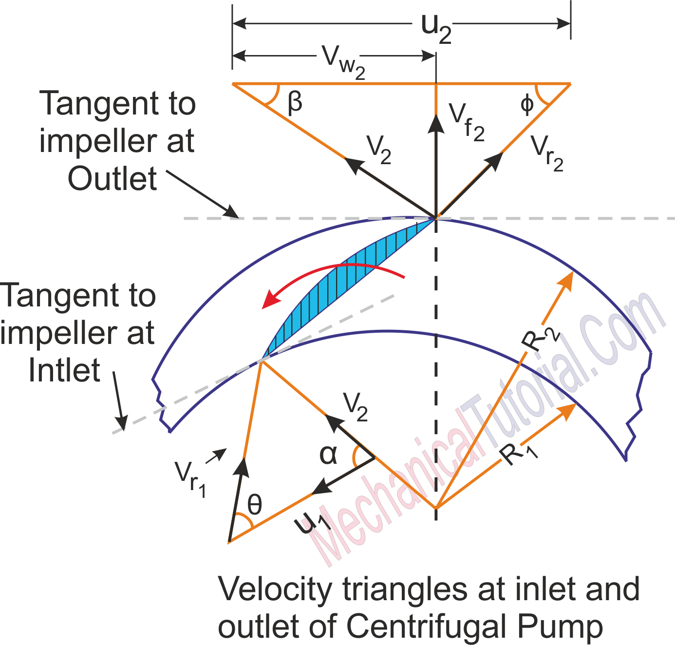
The working principle of centrifugal pump is done by the Impeller on the water. To describe the working of centrifugal pump, we draw a velocity triangle at inlet and outlet of the Impeller seen the picture below. In this picture we can see, the work done by the Impeller on the water is obtained by drawing velocity triangles at inlet and outlet of the Impeller in the same way as for a turbine. Now for the best efficiency of the centrifugal pump, the water enters the Impeller radially at inlet. The velocity of water at inlet creates an angle of 900 with the direction of motion of the Impeller at inlet. Hence angle α = 900 and Vw1 = 0. So, for drawing the velocity triangles, the same notations are used as for the turbines. The diagram shows the velocity triangles at the inlet and outlet tips of the vanes fixed to an impeller.

V1 = Absolute velocity of water at inlet,
Vr1 = Relative velocity of water at inlet,
α = Angle made by absolute velocity ( V1 ) at inlet with the direction of motion of vane,
θ = Angle made by relative velocity ( Vr1 ) at inlet with the direction of motion of vane, and V2,Vr2,β,θ are the corresponding values at outlet.
As the water enters the impeller radially which means the absolute velocity of water at inlet is in the radial direction and hence angle α = 900 and Vw1 = 0.
A centrifugal pump is the reverse of a radially inward flow reaction turbine.But in case of a radially inward flow reaction turbine, the work done by the water on the runner per second per unit weight of the water striking per second is given by the following equation:
Work done by the impeller on the water per second per unit weight of water striking per second
Work done by impeller on water per second
Where, W = Weight of water = ρ × g × Q
Where, Q = Volume of water
and
Where B1 and B2 are width of impeller at inlet and outlet and Vf1 and Vf2 are velocities of flow at inlet and outlet.


